10+ dfd diagram level 0
In the New Diagram window select Use Case Diagram and click Next. A data-flow diagram is a way of representing a flow of data through a process or a system.

Level 1 House Plans Colonial House Plans Country Style House Plans
Sebelum ke contoh kita bahas dulu sedikit tentang apa saja jenis dari DFD yaitu.

. Read through the diagram and then we will introduce some of the key concepts based on this diagram. For maturity levels. At this level there is only one visible process node that represents the functions of a complete system in regards to how it interacts with external entities.
262 Power-up conditions The VCC voltage has to rise continuously from 0 V up to the minimum V CC operating voltage. แผนภาพบรบท Context Diagram Level-0 Diagram Context Diagram คอแผนภาพกระแสขอมลระดบบนสด แสดงภาพรวมการท างานของระบบทมความสมพนธกบภายนอก ระบบ. This context-level data-flow diagram is then exploded to show more detail of.
10 nF to 100 nF close to the VCCVSS package pins. O Level DFD for Online shopping website project. It only contains one process node Process 0 that generalizes the function of the entire system in relationship to external entities.
Enter System Use Cases as diagram name and click OK. A data flow diagram DFD illustrates the flow and transformation of data for a particular business process. In the next the so-called first level - DFD 1 - the numbering continues.
The o level dfd describe the all user module who operate the system. It is a graphical representation which is very easy to understand as it helps visualize contents. This DFD was made using ConceptDraw solution designed especially for data flow diagrams development.
The CS System Data Flow Diagram example contains four processes two external entities and four. The DFD is designed to show how a system is divided into smaller portions and to highlight the flow of data between those parts. Systems engineering is an interdisciplinary field of engineering and engineering management that focuses on how to design integrate and manage complex systems over their life cyclesAt its core systems engineering utilizes systems thinking principles to organize this body of knowledge.
Press on Actor in the diagram toolbar. The context level data flow diagram dfd is describe the whole system. This is is easy to explain because a context diagram is a level 0 DFD.
Whitestar UML is a division of StarUML 50 that offers bug fixes and has improved its compatibility with the latest operating systems ie support of Unicode strings or simply being developed and tested on Windows 7 and 8. Its a visual representation of how data flows through a system so you can clearly see where the data comes from where it goes and how it gets stored. Food Ordering System has the following input.
The system is designed and established across the world with input and output at this level. Whether you are in or looking to land an entry-level position. DFD show a further level of detail not shown in the context diagram.
A Data flow diagram DFD is a much more complex representation of a context diagram. The data flow diagram of this type depicts the large system as a solid process and does not input any explanation of its content. A context diagram is a top level also known as Level 0 data flow diagram.
Daftar isi move to sidebar sembunyikan Awal 1 Etimologi 2 Signifikasi 3 Klasifikasi 4 Sejarah 5 Bahasa terkait Toggle Bahasa terkait subsection 51 Rumpun bahasa Jermanik 6 Persebaran geografis Toggle Persebaran geografis subsection 61 Tiga lingkar negara-negara penutur bahasa Inggris 7 Fonologi Toggle Fonologi subsection 71 Konsonan 72 Vokal 73 Tekanan. Here different levels of DFD are shown for Food Ordering System such as Level 0 DFD Level 1 DFD Level 2 DFD and Level 3 DFD. It supports BPMN 20 ERD ORMD SysML.
Below data flow diagram of online shopping site shows the two user can operate the system Admin and Member user. It may be called a database that contains the name type range of values source and. Its designed to be an abstraction view showing the system as a single process with its relationship to external entities.
Level 0 DFD At this level the Input and Output of the system are shown. Here we will see mainly 3 levels in the data flow diagram which are. Data Flow Diagrams are used to represent the flow of data as well as the processes and functions involved to store manipulate and distribute data among various components of the system and between the system and the environment of the system by a specific set of graphical representations.
During the systems analysis a data flow diagram can be of enormous use in identifying where data are shared by various parts of an organization. It also depicts the logical flow of information in a. It is also known as a context diagram.
Process 1 is divided into the first three levels of the DFD. The top-level DFD the context diagram in Figure 1311 actually tells us very little. It helps us to understand the functioning and the limits of a system.
Context level DFD 0 level. This is the most basic type of DFD where all the processes and storage is represented by a single process. It is an ordinary practice - creation of a context-level data flow diagram when starting system development.
To elaborate further from that we drill down to a level 1 diagram with lower-level functions decomposed from the major functions of the system. This could continue to evolve to become a level 2 diagram when further. Level 1 DFD显示了系统如何分成子系统过程每个系统处理一个或多个来自或来自外部代理的数据流它们一起提供系统的所有功能整个.
In level 1 DFD the single process node from the context diagram is broken down into sub-processes. Stores all the details that correspond to the data flow diagram DFD stores processes and flows. Data Flow Diagram represent detailed and well explained diagram of system components.
It represents the entire system as a single bubble. It is common practice to draw a context-level data-flow diagram first which shows the interaction between the system and outside entities. Drag it onto the diagram to create an actor and name it Customer.
The individual outcome of such efforts an engineered system can be defined as a. As these processes are added the diagram will need additional data flows and. The so-called zero level is followed by DFD 0 starting with process numbering eg process 1 process 2.
A context diagram is a data flow diagram that only shows the top level otherwise known as Level 0. This voltage must remain stable and valid unt il the end of the transmission of the instruction and for a write instruction until the completion of the internal write cycle tW. 0-level DFD 1-level DFD and 2-level DFD.
Levels of DFD are as follows. Keep Blank selected and click Next. Level 1 DFD The figure below shows the level 1 DFD which is the decomposition ie.
It indicates that there are three sources outside the company provide data. Learn how you can make a DFD with Lucidchart in just 10 steps. 数据流图或数据流程图Data Flow Diagram缩写为DFD数据流图DFD.
Jenis yang pertama ini sering disebut juga dengan diagram konteks. Break down of the CS System process shown in the context DFD. Some of the benefits of a Context Diagram are.
Benchmark model views are defined in the CMMI V20 Model Appendix B. To create a Use Case Diagram select Diagram New from the toolbar. Data Flow Diagram Level 0 Template Click on image to modify online Level 1 DFDs are still a general overview but they go into more detail than a context diagram.
DFD ini merupakan diagram yang terdiri dari metode yang dpaat menjelaskan secara umum lingkup sistem informasi yang akan dibuat. It is usually beginning with a context diagram as level 0 of the DFD diagram a simple representation of the whole system. Data Flow Diagram Levels.
Draw data flow diagrams can be made in several nested layers. Customers the stores to which the.

The Best Way To Take Notes Imo Looks So Organized Too Nursing School Notes Nursing School Organization Nursing School Survival
Data Flow Diagrams Dfd Example Of Dfd For Online Store Data Flow Diagram Dfd Example Design Data Flow Dfd Library Data Flow Diagram For Restaurant Management System

Structured Analysis Wikiwand

Pin On Project Uml Diagram
Example Of A Data Flow Diagram Level 0 Youtube Data Flow Diagram Flow Diagram Example Business Analysis

Structured Analysis Wikiwand
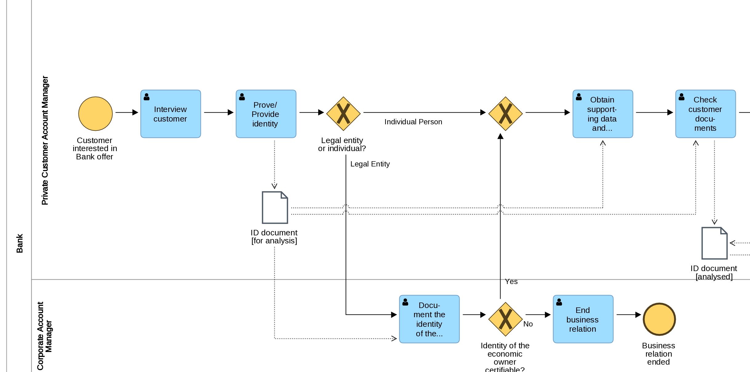
Data Objects In Bpmn Bpm Tips

Event Partitioning Wikiwand
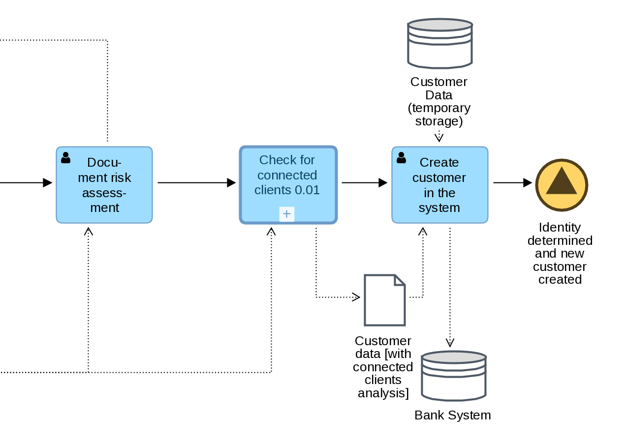
Data Objects In Bpmn Bpm Tips

Database Flowchart Symbols Flow Chart Symbols Basic Flowchart Symbols And Meaning Database Flowchart Symbols

Another Example Perfect Pizza Current Logical Level 0 Diagram Customer Order Customer Phone Number 1 0 Find Customer Re Example Logic Perfect Pizza

Craftsman Style House Plan 1912 Marietta 5 Sets Craftsman Style House Plans House Plans Craftsman House
Data Flow Diagrams Dfd Example Of Dfd For Online Store Data Flow Diagram Dfd Example Design Data Flow Dfd Library Data Flow Diagram For Restaurant Management System

Context Level 0 Data Flow Diagram Template Data Flow Diagram Diagram Context

Pin On S

Data Flow Diagram Templates To Map Data Flows Creately Blog Data Flow Diagram Diagram Design Diagram

Event Partitioning Wikiwand